


879
What is selective coordination & how to create coordination curves.
Selective Coordination is a design requirement added by 2005 National Electrical Code to Article 700 - Emergency Systems (see 700.27), Article 701 - Legally Required Standby Systems (see 701.18), and by the 2008 NEC to article 708 - Critical Operations Power Systems (see 708.54). These articles also apply to Health Care Facilities as noted in 517.26. Prior to 2005, Selective Coordination was only required for some elevator applications by Article 620. For sections of systems falling under Articles 700, 701 and 708, the Engineer is responsible for selecting overcurrent devices such that only the device directly upstream of the fault will trip. This differs from traditional typical coordination and coordination studies that attempted to minimize only the chance of nuisance trips where a fault may open more than one device.
To design a selectively coordinated system, the engineer must choose pairs of overcurrent devices whose time current curves do not overlap in either the thermal range or the instantaneous range up to the current available at the downstream breaker. Example: A 20A branch breaker egress lighting per 2005 NEC 700 must selectively coordinate with all upstream devices. The 20A breaker is in a branch panel that has 2500A of available fault current. To selectively coordinate, only the 20A breaker may trip under this fault - this means that the next upstream device must not trip with 2500A of current prior to the 20A device opening. The smallest device with an instantaneous trip that will not operate at 2500A (including the tolerance band) is a 400A thermal magnetic or a 300A solid state circuit breaker. That second breaker must in turn coordinate with the next upstream device at the fault current level available at that second breaker, and so on, up to and including service entrance overcurrent device. When the system is being powered by the emergency source, the coordination must now be calculated based on the new available fault current, in most cases sources from an emergency generator.
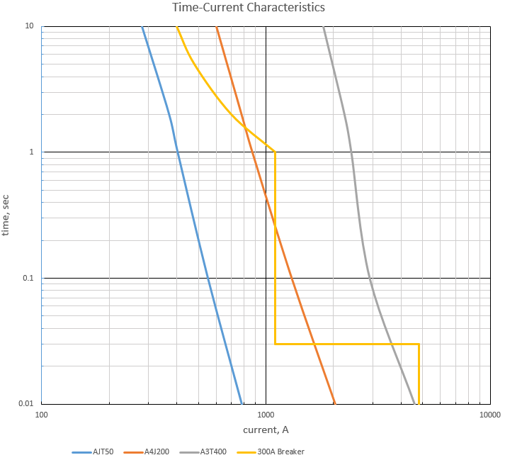
If you are an electrical engineer doing protective devices coordination on a daily basis than it makes sense to consider purchasimg a commercial software license and let the program to create selective coordination charts for you. However, if you are doing selective coordination studies occasionaly only, than spending money to purchase an expensive software program may not be feasible. Time-current curves can also be plotted and selective coordination for any particular application can be verified by using MS Excel. The graph below has been created using Excel charting tool. Feel free to download the original worksheet and use it as a template for drafting your own selective coordination charts.
Disclaimer - Please Read
This spreadsheet is indended to provide technical and basic design information for the user. ARCAD INC. reserves the right, without notice, to change information or data originally in this spreadsheet and to discontinue or limit its distribution. The data and information presented in this spreadsheet is believed to be accurate. However, any and all liability for the content or any omissions from this spreadsheet is expressly disclaimed. ARCAD INC disclaims any liability related to the use of this spreadsheet.
Copyright © 2019 ARCAD INC. All rights reserved.